CANInsight Logger

Project scope: Custom CAN logger design, implementation, testing and deployment. Build data processing pipeline to handle incoming log files.
Background
CAN data logging is a critical part of vehicle design and testing. In order to troubleshoot issues and validate designs a CAN logging device should be used. Most CAN logging devices are either too expensive or do not have a great feature set. For example this can logger on tindie is quite inexpensive but lacks a proper case for mounting, does not have a realtime clock, and is frequently out of stock. In contrast the next-cheapest alternative I could find is the CCS Elecronics CANEdge priced at 169-449 Euros depending on the model, with RTC functionality costing at least 229 euros. The goal of this project was to design and build a feature-rich CAN logging device at a lower price point.
Design Process
The idea for this project has developed over a few years, through the process of designing mining vehicles my knowledge and experience working with CAN bus technology has improved vastly. While troubleshooting issues on a few machines I quickly realized the benefit of being able to capture and graph data being sent over the CAN bus. Eventually I found and ordered a CCS Electronics CANEdge, this device worked very well but was a bit complex to set up, not designed to be bolted to a surface, had DB9 connectors (not IP rated), and had more programming features than I could or would use. The outstanding feature of the CANEdge was the ability to graph data using the open-source ASAMMDFGUI tool, this was critical for fixing a few machines and I knew I wanted to keep using the graphing features moving forward.
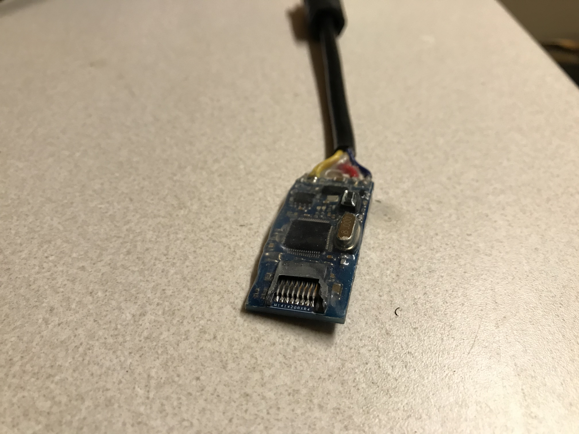
Next I found the CAN logger from Tindie and ordered a batch, I put a custom pigtail with a 5-pin M12 connector to fit on the machines that I was testing (image below). Although very cost effective the lack of onboard real-time clock was severely limiting for these devices. I could not expect to know what time certain events were taking place on the vehicle. RTC functionality was especially important for obtaining customer feedback, when customers would say "the issue happened on this date" the log files could not easily be consulted to determine the issues or root cause because I had no idea when any of the data was recorded.
Based on these experiences the design requirement groundwork was laid, my device would need to log CAN signals in a format that could be viewed in ASAMMDFGUI, correlate log files to datetimes, and be relatively low cost.
I was not considering a custom build for this project until I came across the Teensy 4.1 development board. The Teensy 4.1 provides 3 CAN interfaces, a builtin SD card, and very easy implementation of RTC. The combination of features on the Teensy was exactly what I needed to make this project work, and at a cost of around $45 CAD the teensy would not significantly inflate the budget.
Prototyping
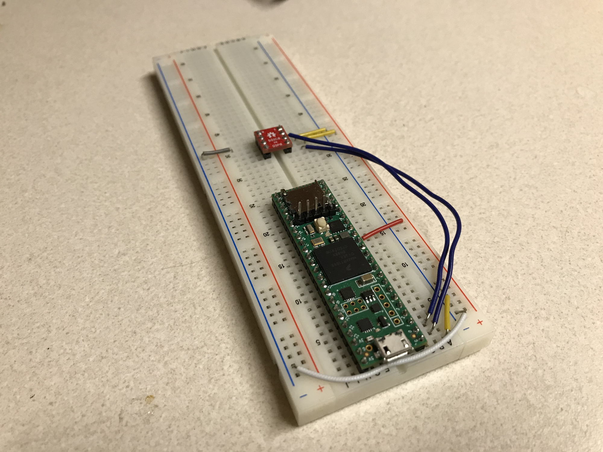
To validate the idea I ordered a Teensy 4.1 and a few CAN transceiver chips. I put them together on a breadboard and wrote some basic code to receive CAN messages. Using an CAN to USB adapter I sent and received some messages. Using the basic CAN functionality on the teensy was surprisingly easy and straightforward. I setup an interrupt function to trigger every time a new message was received and from there began writing data to the SD card.
The next step was to test the RTC, again this was fairly straight forward after finding some examples online. Finally, logging data to the SD card was the last step. Data logging was a bit more confusing because of the SD libraries and took some tries to get just right during testing but the initial version was very basic.
Implementation - V1
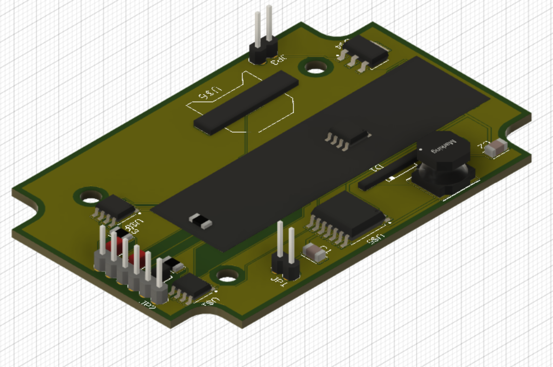
After prototyping I was confident that the teensy would work well for this project. In the past I had built circuits on prototyping breadboard but since I wanted this device to be compact and reliable I needed to use a real PCB. Initially I attempted to use Fritzing, an open-source software for circuit and PCB design. I quickly realized that this tool was not sufficient and was far too complex to do even simple projects easily. At MineMaster we use the Autodesk suite and I found that Fusion360 had extensive circuit and PCB design functionality. I spent a full weekend learning Fusion360 and prototyping an initial design. After a steep learning curve and many hours watching YouTube videos Fusion made the PCB design process an absolute breeze and even automatically created 3D models of the design!
My mandate for the initial implementation was to design a simple PCB to fit in an off-the-shelf plastic case. Mechanically, I wanted a case sealed against dust and splashing water as well as a surface-mountable option so that it could be installed in a piece of mobile equipment easily. I also wanted to use strain-reliefs to reduce possible stresses on the soldered connections to the breadboard in case the cables got pulled. Electrically, I needed to have a wide voltage input rage, as our machines run on 12V or 24V electrical systems. I also wanted to support all 3 CAN channels and the Realtime clock.
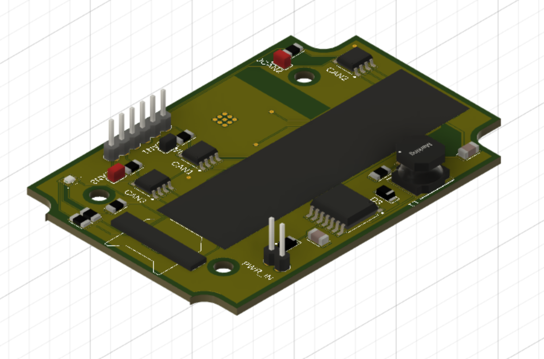
The final result was the following design. It uses a TI buck converter to reduce the input voltage down to 3.3v, with a backup SOT223 space for a standard linear voltage regulator in case the TI device did not work as expected. The design features space for three CAN transceiver chips, each with its own 120 Ohm termination resistor and solder jumper for configuring the resistor. Finally, this board has space for a CR1220 battery to power the Realtime clock.
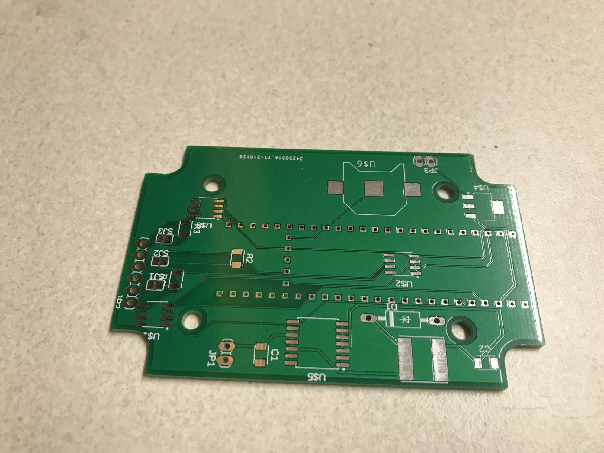
When the PCBs arrived it immediately became obvious that I made some beginner mistakes. I managed to get one unit working but quickly realized that a second revision would be needed.
- The RTC battery pins were backwards, I failed to look at the pinouts and made the wrong assumption.
- The through-holes for the teensy headers were too small, meaning that the board would need to be soldered on top like an SMD component.
- I ordered the PCB in one-layer instead of two, this wasn’t a dealbreaker because the teensy through-holes were too small anyway, but all components needed to be soldered on the top of the board which is not how through-hole components typically work.
- CAN3 transceiver was connected to the wrong pins on the teensy.
- I didn’t leave space for the strain relief, I ended up cutting the PCB to accommodate the strain relief in the box.
After licking my wounds and learning a few lessons I managed to get the device working, tested the functionality on the bench and was ready to connect it up to a real vehicle.
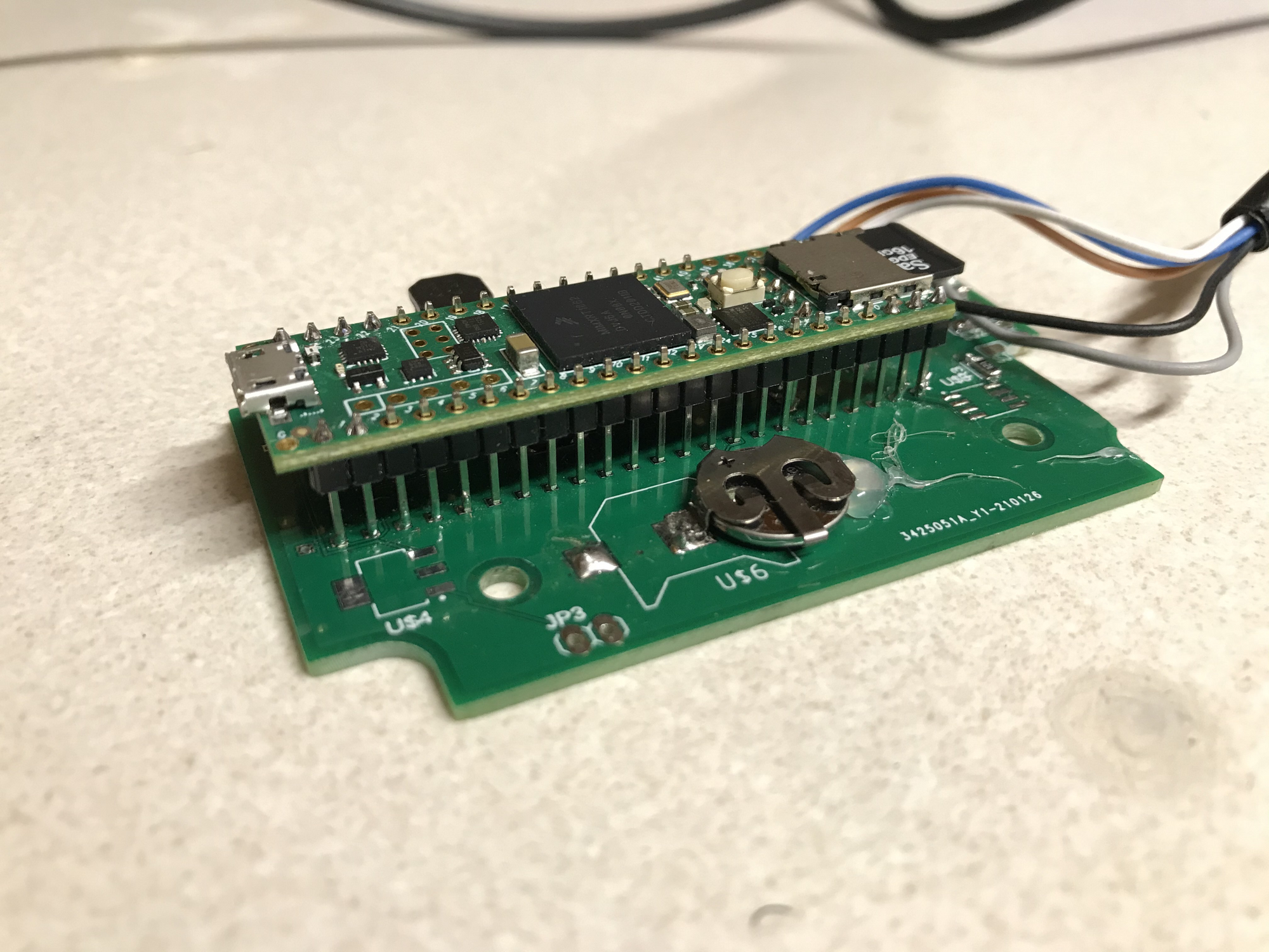
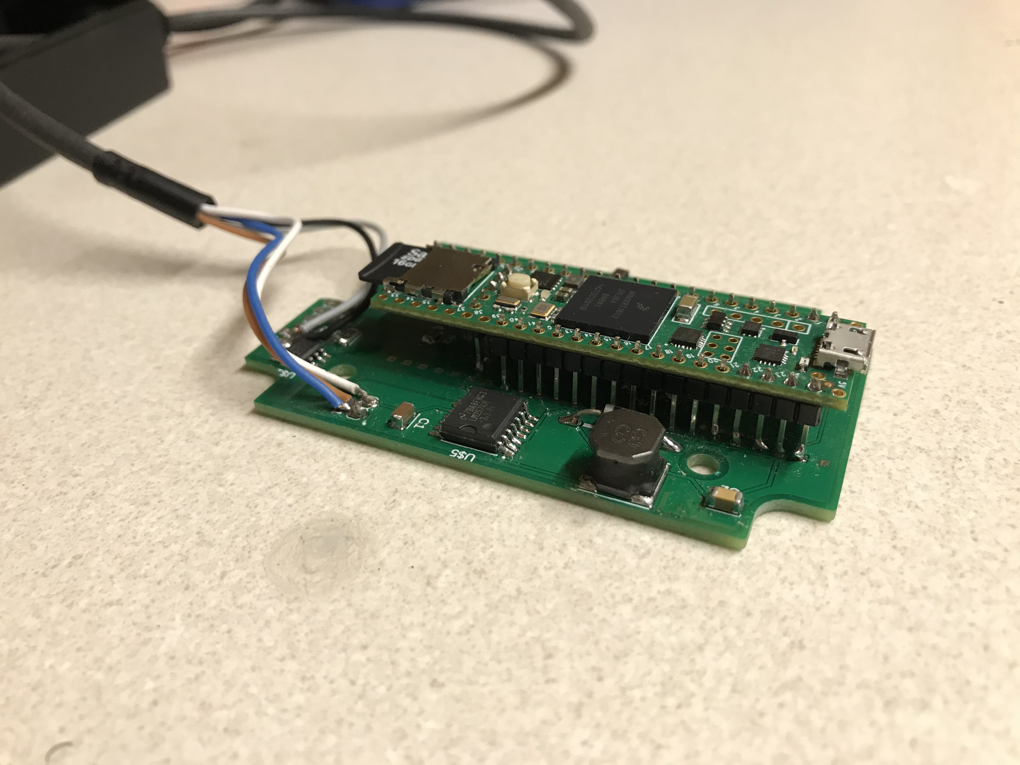
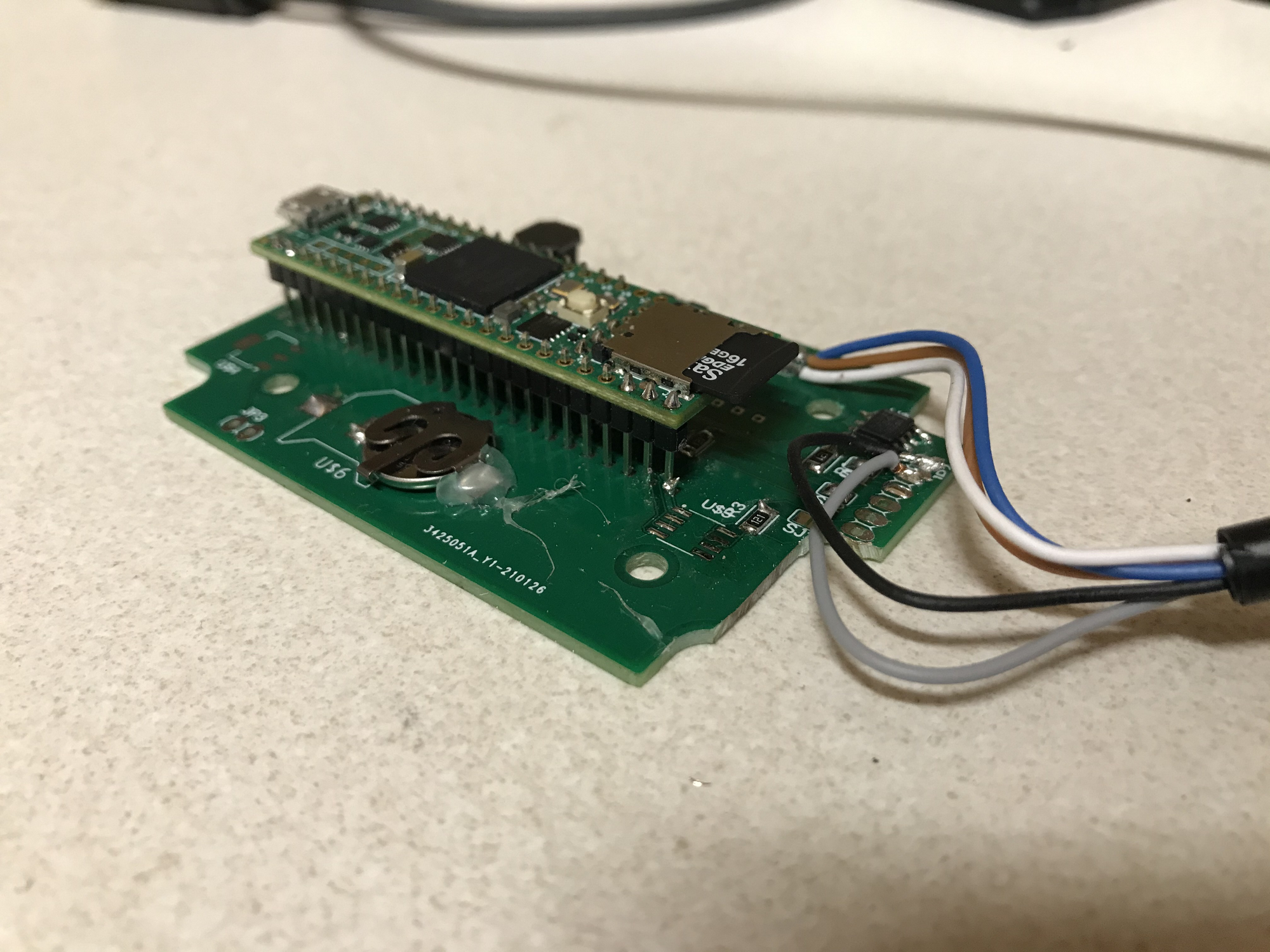
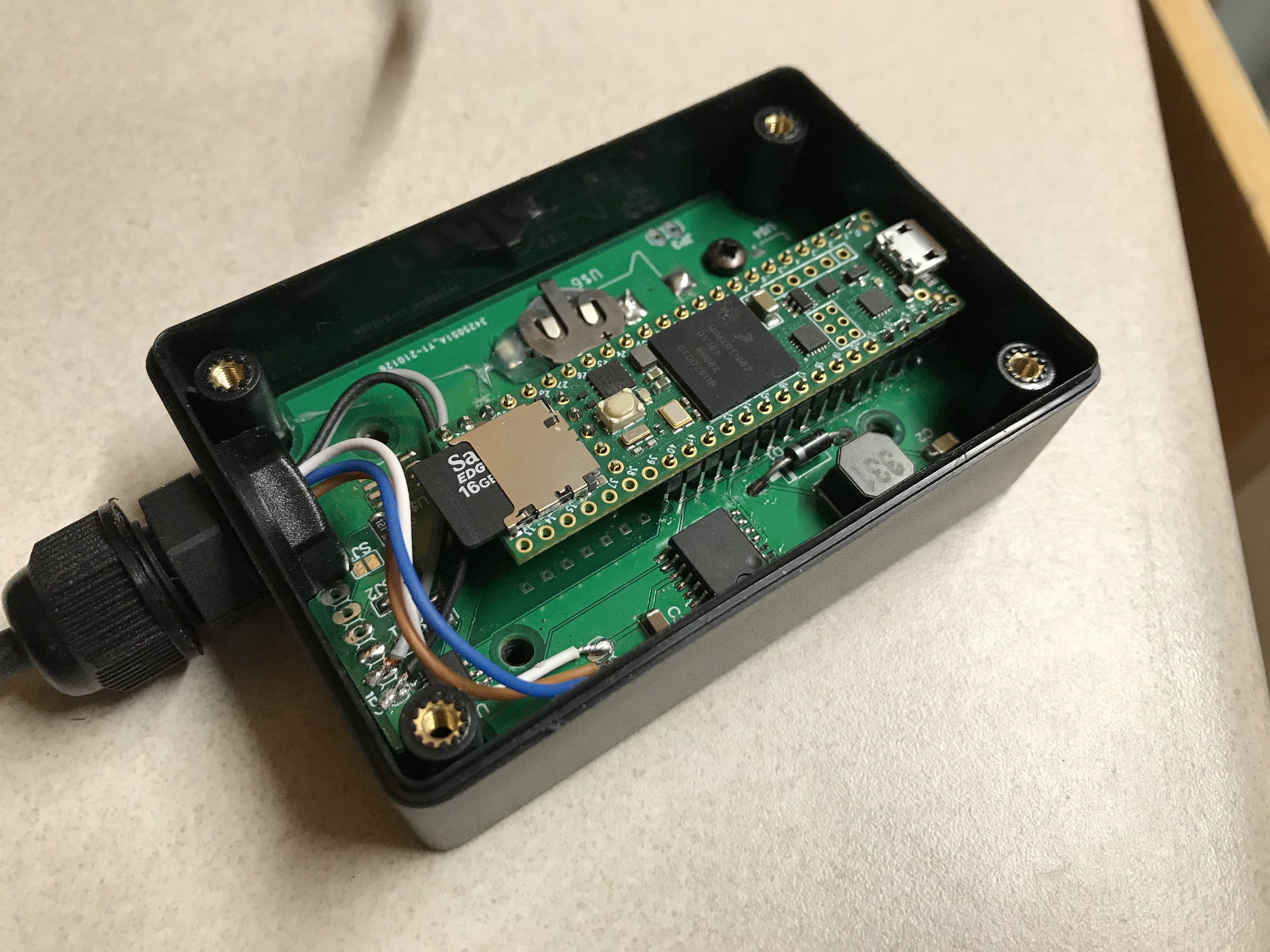
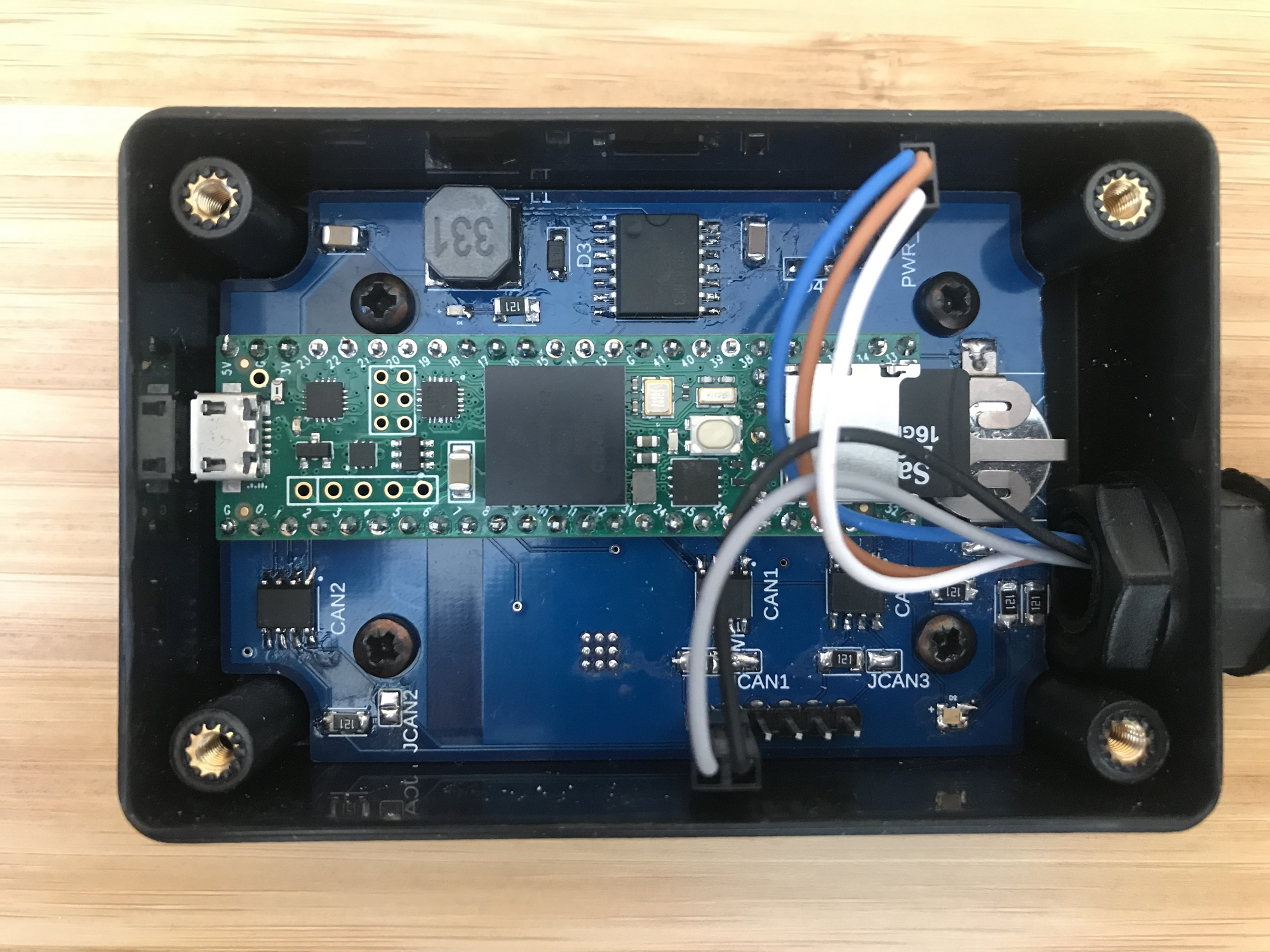
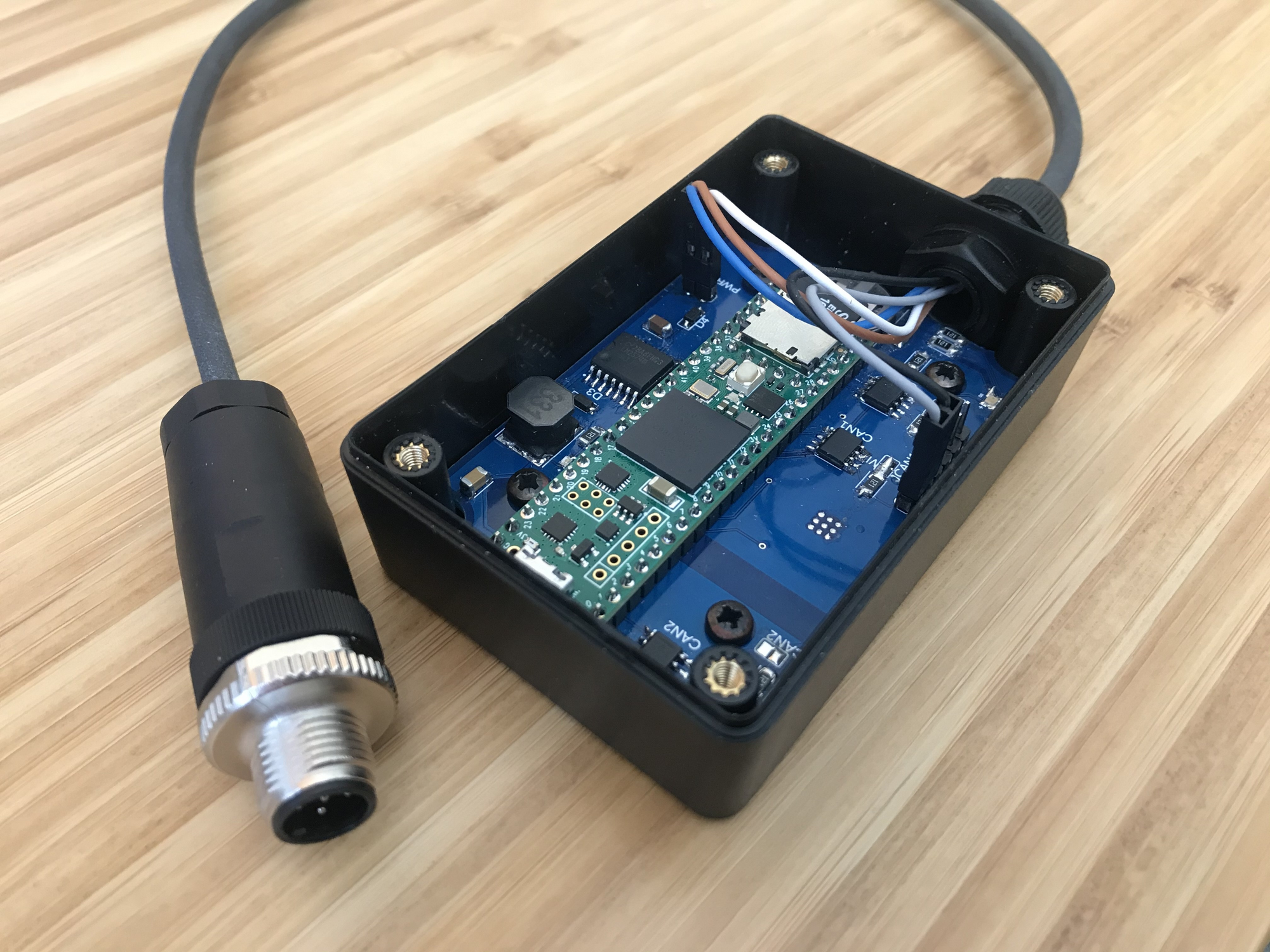
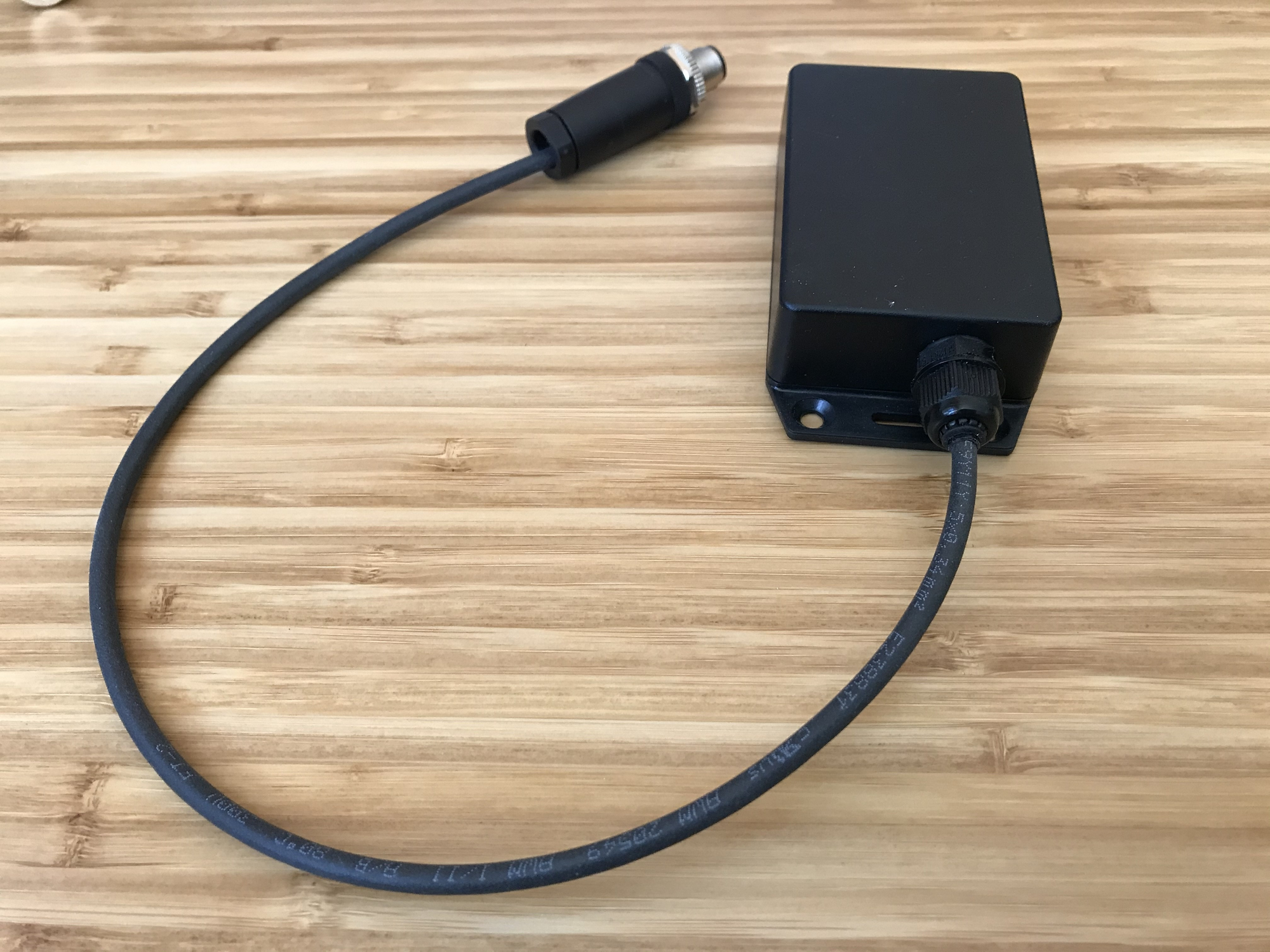
V1 build photos
Testing
Testing the unit revealed a lot of small bugs in the code, all of which were fixed easily. For example when testing on the bench no CAN message was received before the RTC had initiated. With the device installed on a vehicle the CAN logging began before initialization was complete, resulting in a crash every time. Also, opening and closing the file for reading when every single CAN message was received was far too cumbersome and resulted in lost frames. A write buffer was added to the SD card to enable batch-writing of data at longer intervals. These minor code updates were done iteratively as the issues were discovered.
I also quickly thought of a few important hardware features that would be desirable in V2. Reverse polarity protection and status LEDs were noted as crucial components for the second set of boards.
Also during testing of V1 I built the log processing system to automatically ingest and process log files which is super useful, more on this in the section below.
Implementation - V2
For V2 I modified the circuit and PCB in Fusion360 based on lessons learned. The same enclosure was used since the physical size of it was perfect for fitting all of the required components. I made the PCB slightly smaller to properly fit two M12 strain reliefs on the end without requiring cutting into the board to make it fit. For V2 I also added provisions into the PCB to support a wifi chip. The functionality and code for this addition has not been thought out, but in the future I will investigate the possibility of including wifi functionality and having the pads for a wifi chip did not increase the cost of the PCB.
When the PCBs arrived I quickly built the first one. I was nervous soldering the tiny LEDs which are much smaller than the 1206 resistor but I was surprised at how easy the small components were to solder by hand with the help of a pair of electronics tweezers.
Once the first board was assembled I went to work programming the status LED. Since I bought an RGB capable LED I was easily able to create different statuses using orange, red, green, and blue colors. In order to simplify the BOM for the project I used the same 120 ohm resistors for the LEDs as I used for the CAN termination resistors, Initially the LEDs were so bright that they all appeared as slightly different shades of white. I quickly added a PWM function to the ports and turned the brightness down to an acceptable level to distinguish between the colors easily.
Also in V2 were some more code updates, I split the functions into different files to reduce the size of my main.cpp which was rapidly approaching 400 lines of code. I tested logging when the SD card got full and the number of files increased beyond the 9999 supported files. I found that when there were more than about 100 log files the boot time increased significantly as the program attempted to open every single file sequentially until the next available filename was found. I added an EEPROM function to save the next known file to non-volatile storage so that the boot times would be significantly faster and this worked very well.
If you are interested in getting your hands on a CAN logger check out my Tindie store: https://www.tindie.com/products/perspic/caninsight-logger/
Log Processing
Logging data is only useful if you can answer questions and gain insight from the data, and this project started with this goal in mind. So how can we go from raw CSV data to answering questions?
The CAN Insight device logs data directly to a CSV format. CSV was used since it is very widespread, easy to implement, and easy to view on any device. Although CSV files are easy to view, the raw CAN data is almost always meaningless to a human so some translation is needed to obtain “physical values” from the data and this is where the log processor comes in. (Physical values are values in physical units, such as hydraulic pressure or vehicle speed). Another disadvantage of the CSV format is that CSV files are larger than the ideal case because of the inefficient encoding. However, since large SD cards are relatively inexpensive I consider this to be a cost worth incurring for simplicity. A future milestone on my unofficial roadmap is to find a library to write a more compact format (probably .MF4) directly on the logging device.
For this project I wanted to start simple and build a system to create and store .MF4 files from the raw CSV logs. The .MF4 format is excellent because it is compact, easy to transform into physical values, and easy to display/graph with open-source software. The solution that I came up with was a docker container which searches for new files every 10 seconds. If new files exist in the input folder the system automatically converts them to .MF4, translates them with the respective .DBC files, and saves them in unique folders for each project and specific unit serial number. Docker is great for this because volume management in the virtual environment means that you can point the docker container at any folder. For example a remote repository with terabytes of storage could be used to store the logs but the docker container can still be run on a workstation computer.
I found that when using other logging devices a missing piece of the data logging ecosystem was an easy and consistent method for storing data log files. We are working on many different project types and numerous machines of each type so data logs can easily get lost or put in the wrong place. The Log Processor attempts to solve this by creating a directory structure that is easy to browse. Currently the structure is \out\<unit_type>\<unit_number> and all log files are saved with a date in their file names. This way files for a specific project, unit, and time can easily be found and referenced.
The next step for the Insight Log Processor is to build in “artificial intelligence” to answer questions without manual input. For example, on a Battery Electric Vehicle the state-of-charge usage over time is a critical parameter of vehicle health. Automatically searching for anomalies in the battery or producing reports such as “the average runtime was 2 hours and average distance was 40 km on a charge” will be important for future iterations of the project.
Check out my github for the log processing project: https://github.com/puregame/CANInsight-processing
Final Thoughts
I had a blast building this project. The intersection of design, engineering, testing and ending up with a useful final product (even if just for my own purposes) has been a lot of fun. Learning about new technologies and techniques, ordering my first custom PCB, trying SMD soldering, and programming in C on the teensy has been a challenge worth undertaking. I’m sure there will be more bugs to fix along the way but I hope to continue refining this project to a point where it will be useful to someone else. If you or someone you know is interested in trying it out please check out the tindie store or send me an email at matthew@tracksandwheels.com
References and Links
Enjoying these posts? Subscribe for more
Subscribe nowAlready have an account? Sign in