Wyze Cam V3 Hacking with Raspberry PI

Background
I have a few Wyze Cam V3s (WCV3) and I have been quite happy with them so far, they perform well and seem to be pretty reliable but I’ve had two failures so far. The first camera failed after about 2 weeks of use 8 months ago, Wyze replaced it. The replacement unit and the other 4 I have worked just fine for a while now. Last month I tried using the RTSP firmware from Wyze and it bricked another camera. Wyze support was outstanding and after doing some basic troubleshooting offered a replacement each time. After getting replacement units from Wyze and getting to keep the originals I decided to try to tear them apart and see if I could fix them. This is the story of what’s inside a Wyze cam V3 and how I used a raspberry pi to explore the Wyze Cam V3.
Tear down
For pulling the WCV3 apart I referenced this youtube vide: Wyze Cam V3 Unboxing and Teardown | Mine died, what's inside? Taptic digital does a better job than I could so check out his video. The tear down is pretty simple and requires a sharp knife and screw driver. I didn’t go farther than removing the camera assembly from the case but if you’re interested you can take the first board off as shown in the video.
In the references section below there is a link to the FCC documentation for the Wyze Cam V3, this shows internal photos of the unit as well.
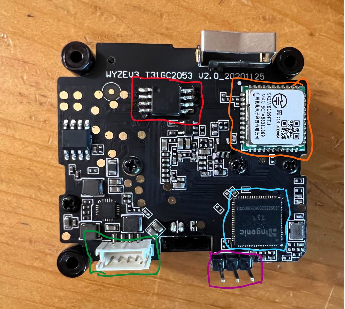
What’s on the board
- CPU: Ingenic T31 (highlighted blue)
- Flash Memory (highlighted red)
- Wifi Chip (highlighted orange)
- USB Header (highlighted green)
- Serial Port Pins (highlighted purple) (with header soldered by me)
- Image sensor: GC2053 (other side of the board)
Reading From Flash Chip
The writing was faint but with a powerful light I was able to read the writing on the flash chip, the chip is an EON EN25QH128A128 megabit serial flash memory chip. I’ve used flashrom on a raspberry pi before so I wanted to try to connect to the chip and see if I could read the data.
First I tried to use a SOIC8 chip clip to program the chip directly without removing it from the PCB. Sometimes this works but it did not work on the WCV3. Next plan: I had to desolder the chip and solder it onto an SOIC8 breakout board. Once the soldering was done I connected the chip to the raspberry pi using the below pin mappings.
For testing purposes I added breakout lines to the WCV3 PCB where the memory chip is mounted. This allowed me to quickly move the memory chip between the PI and the camera. The soldering to add these lines was difficult as the SOIC8 chips pins are quite close together but it was worth it to be able to move the memory chip and test multiple different firmware flashes.
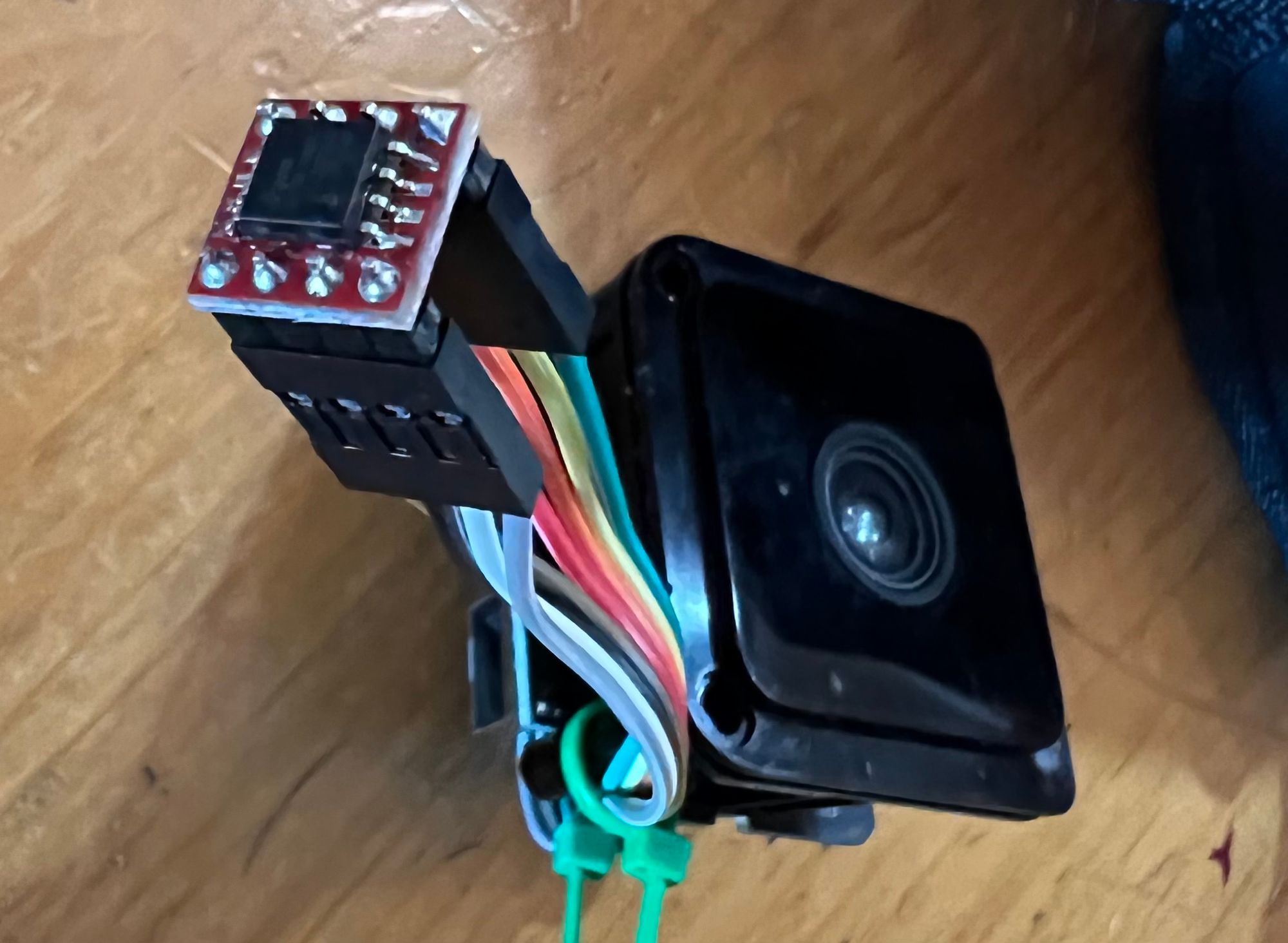
SOIC8 breakout board connected to camera via breakout lines.
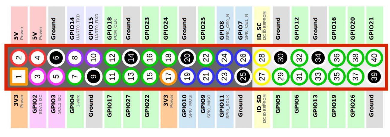
Pin Mappings
RPI Pin |
Chip Pin |
SPI Description |
|---|---|---|
25 | 4 | GND |
24 | 1 | CS |
23 | 6 | SCK |
21 | 2 | DO |
19 | 5 | DI |
17 | 8 | VCC |
13 (IO27) | 7 | HOLD |
15(IO22) | 3 | WP |
GPIO for HOLD/WP
To read and write to the chip we need to pull HOLD and WP pins high, I didn’t have an easy way to Y the wires together so I used some GPIO pins. To set the pins high first set them as output (op) then set them to drive-high (dh).
$ raspi-gpio set 22 op
$ raspi-gpio set 27 op
$ raspi-gpio set 22 dh
$ raspi-gpio set 27 dh
Enable SPI through GPIO Pins
First, enable the spi interface via raspi-config. Then check spi availables
$ ls /dev/*spi*
I know the one I’m looking for is /dev/spidev0.0 for the main SPI on RPI 4b. Using a different RPI may require a different SPI device.
Use flashrom to read chip data
First, confirm the chip is connected properly by running the following command and ensuring the chip shows in the output, if the chip doesn’t show up check wiring.
$ flashrom -p linux_spi:dev=/dev/spidev0.0,spispeed=512
If this command succeeds you will see the device type in the output.
To read the flash data use
$ flashrom -p linux_spi:dev=/dev/spidev0.0,spispeed=8000 -r wyze_rom.rom
Note: maximum speed for RPI 4 is apparently 8000 = 8Mhz, it takes about 8-10 seconds to download entire memory for me at this speed.
I would recommend downloading multiple times and comparing files with checksum. If all sums are the same then no data transfer issues occurred!
$ sha256sum *
Next I used binwalk to review the different parts of the bin/rom file. The -e option will extract the data to folders. (Note you will need jefferson to extract JFFS2 portions of the ROM)
$ binwalk wyze_rom.rom
For more see this youtube video: IoT Security: Backdooring a smart camera by creating a malicious firmware upgrade. In the video he uses the firmware downloaded directly from wyze, but the same methods and commands are applicable to the firmware taken directly off of the camera using flashrom.
I extracted the data to folders and went through it quickly, I didn’t find anything too exciting that wasn’t in the video above. I did however notice that one of the blocks is an “Android”, I guess the WCV3 runs on android!
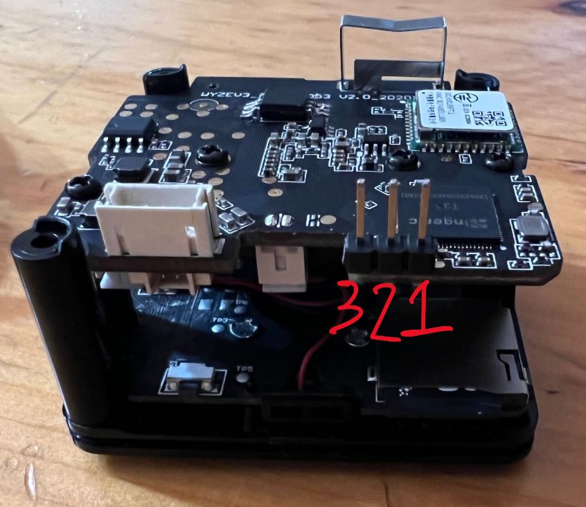
Logging in via serial
As mentioned above the WCV3 has a serial header connection, I found information on this header on github. After soldering the header pins and connecting to the RPI I used screen to open a terminal session on the serial bus.
Pin Mappings
RPI Pin | WCV3 Pin | Function |
|---|---|---|
6 | 1 | GND |
10 (RX) | 2 (TX) | RX/TX |
8 (TX) | 3 (RX) | TX/RX |
NOTE: use raspi-config to enable the serial interface and make sure to disable the login shell! Reboot to apply the configuration.
Next I installed screen and connected to the camera
$ apt update && apt install screen
$ screen /dev/serial0 115200,cs8
Now we can see the terminal output directly from the camera! Below is the boot data from one of my cameras.
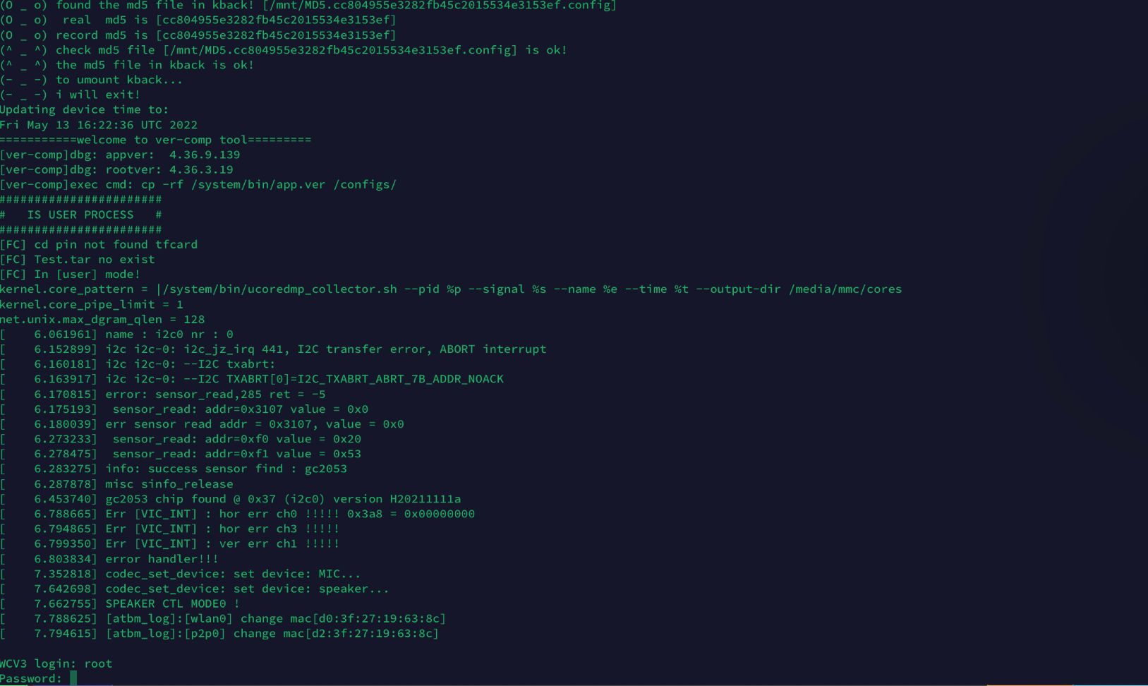
I had two cameras, one I could not get the password for, the other I did get the password. The one with older firmware worked with username “root” and password “WYom20200”. My guess is Wyze has done a firmware update to a more secure password since then. If you want a copy of the ROM that password WYom20200 works reach out to me.
After logging in I could browse the directory structure and view all of the files. When the unit is connected to wifi I could ping google which is kinda cool. I find it fascinating to be able to get a root login shell on a $50 CAD security camera. The whole world really does run on linux.
ROM Investigation
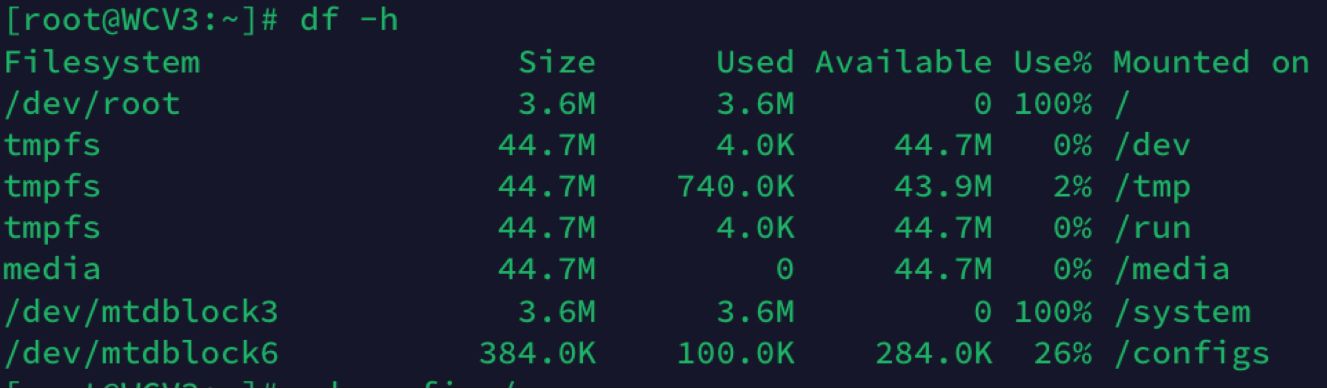
As mentioned above I did some poking around on the ROM images that I downloaded from each camera. I also checked “df -h” on the camera I could log in to. This shows a few different memory areas are mapped to different directories. From what I found all directories but /configs are read-only folders. I couldn’t find where the wifi network and PSK are stored. I don’t know how the ROM image gets mounted so I wasn’t sure how these directories map to the memory image I downloaded and investigated using binwalk.
Fixing the Cameras
As mentioned I had two failed cameras, one I was pretty sure caused by a firmware issue. I figured if I could update the firmware it may work again.
Camera 1
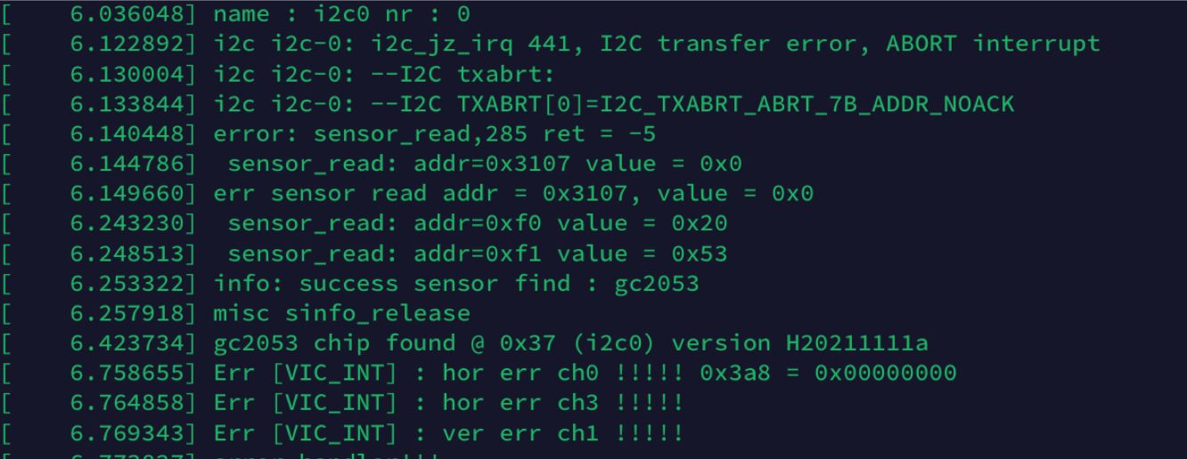
Camera 1 failed months ago, it has an old firmware and password “WYom20200” worked. When I connected to the serial port this camera shows a few hundred lines of i2c errors. From what I can tell these errors are communications errors to the image sensor chip, it looks like the CPU is attempting multiple connections to different i2c addresses and and they are all failing. My guess is the image sensor failed and isn’t communicating anymore. In the future I may try to tear this device apart further and fix this but for now this issue is beyond my pay grade.
Camera 2
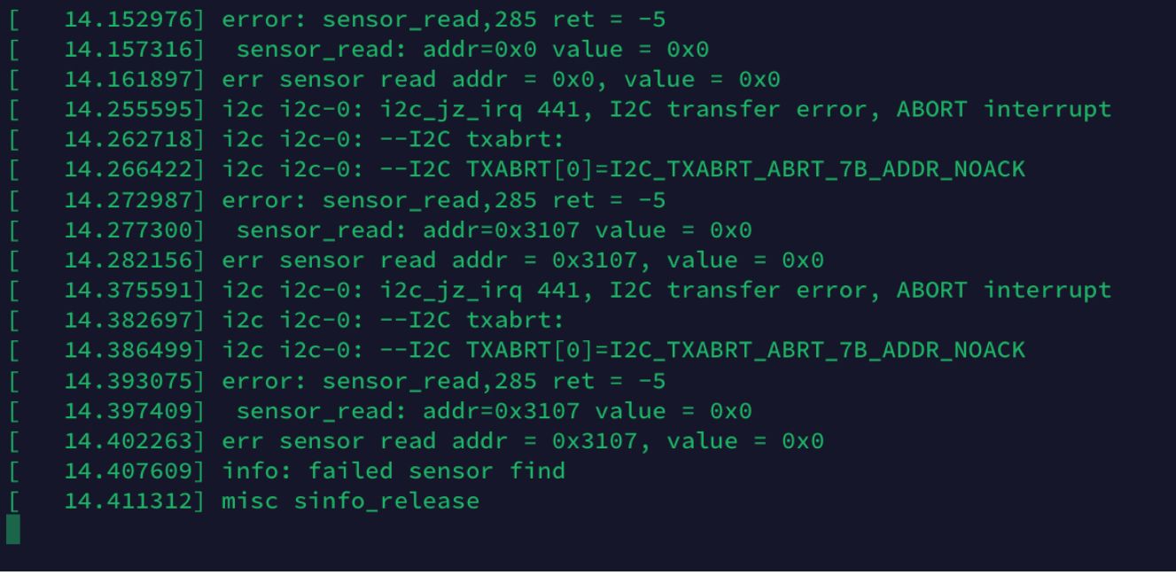
Camera 2 is the newer one, a few weeks ago I tried to flash it with the Wyze RTSP Firmware which seemed to work for a little while but after a few minutes the camera wouldn’t respond. When connecting to the serial port the camera shows a different sensor read error so I thought it would be dead too. Just to try I uploaded the firmware data that came from the old camera. I got the same error messages but the camera showed some data every time the speaker said “ready to connect”. Seems like it might actually be working…
I generated a QR code on the wyze app and the camera found the QR code! After it connected I saw some other messages about wifi connecting etc. Sure enough about a minute later the camera was up and running in the Wyze app! Succcess!
I also noticed that as soon as the camera connected to the wyze app and started streaming video data the CPU chip got quite hot, not surprising but interesting that the video streaming does tax the cpu quite heavily.
Conclusion
When technology stops working it can be incredibly frustrating. It always felt to me like such a waste to throw things out when they stop functioning properly. Luckily these days you can fix a lot of issues with some inexpensive hardware, google skills, open source software, and determination. I hope this blog is useful to someone, if you have a dead Wyze cam V3 from a failed firmware update you may be able to revive it!
Even though I got one camera working there is still more I would like to do with the Wyze Cams. Below is a short list of things I would like to try, since the WCV3 runs on android/linux OS the sky is really the limit here.
- Find i2c logs on Camera 1 and see if the sensor issue is fixable.
- Crack the new password in the latest wyze firmwares
- If can't crack the password, unpack and repack a memory dump with a new shadow file and new password.
Useful links
Youtube Video: Wyze Cam V3 Unboxing and Teardown
Youtube Video: IoT Security: Backdooring a smart camera by creating a malicious firmware upgrade
Github Issue overview of WCV3 Serial Port
Wyze RTSP Firmware
FCC documents for Wyze Cam V3
Jefferson installation instructions
Flashrom for rpi
T31 CPU Datasheet
GC2053 Image Sensor Datasheet
EON EN25QH128A Memory Datasheet
Materials Required
- Raspberry Pi (any will work)
- SOIC8 chip clip
- SOIC8 breakout board
- Header Pin Connector Wires
- Soldering tools
Enjoying these posts? Subscribe for more
Subscribe nowAlready have an account? Sign in