CAN Isolator - Idea, Design, Testing

Final product: Perspic CAN-ISO-2500 Product Page
Background
At MineMaster we design and build state-of-the-art mining equipment. A recent project was the MM1140EV - a battery electric 4-person utility. This project required a CAN Bus isolation deice to isolate the high voltage motor controller from other CAN Bus devices. On the machine the drive motor is powered by a 100v battery package but the controllers and displays are powered by an isolated 12v power supply. Since the power supplies are galvanically isolated the CAN Bus lines acted as a current path between the two otherwise isolated circuits. In some scenarios the voltage difference was enough to cause the CAN transciever chips in the motor controller to fail and the motor controller would become completely unusable.
After some research and investigation we found that CAN bus isolaion devices exist and could be integrated into our machine to isolate the two sides of the bus and prevent voltage transients from frying the CAN transciever chips.
Existing options included the PCAN Optoisolator, Whitebream Canbus Repeater, and a few others. These devices were not well suited to our application for a few reasons: none were IP rated for water resistance, many required a 5v power supply which is not easily available on our machine, some only supported baudrates up to 250 Kbit/s, and others required configuration and setup to work properly.
After evaluating the options we decided to temporarily use the PCAN Optoisolator while evaluating our own custom device to meet all of our desired criteria.
Device Requirements
- CAN speeds up to 1Mbit/s
- IP Rated enclosure, at least IP54
- Wide input voltage range, at least 14 Vdc max, ideally 28 Vdc maximum input voltage
- No configuration or setup required, plug and play for multiple bus speeds
Research
After deciding to do our own design we started researching other similar designs to reference. We found the ADM3053 isolated CAN transciever from Analog Devices that supports isolation up to 2500 V. This chip was preferred because of the integrated power transmission function which eliminated the need for a second isolated power chip. Next we found a plastic enclosure from Hammond Manufacturing that is IP54 rated and started designing the PCB .
Initial Design
The first design was extremely simple and didn't have any arbitration logic, so as soon as any device transmitted the bus would lock up in the dominant state. we quickly realized this error and researched options for arbitration between the two CAN transcievers to solve the problem
After finding these errors we also found a TI reference design for the bus arbitration logic to allow two CAN transcievers to be installed back-to-back with no requirement for a microprocessor to decode and re-encode the CAN data.
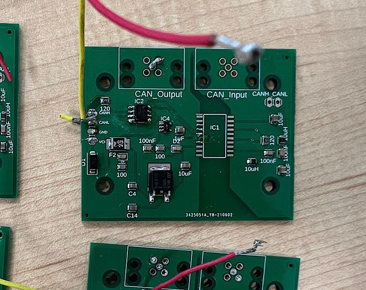
Next we designed a board with arbitration logic and tested it. After some growing pains of wiring issues and soldering the board worked on the test bench.
After the second design was tested on the bench we planned a more comprehensive series of tests to validate the performance over a wide range of environments.
Testing
Testing Setup
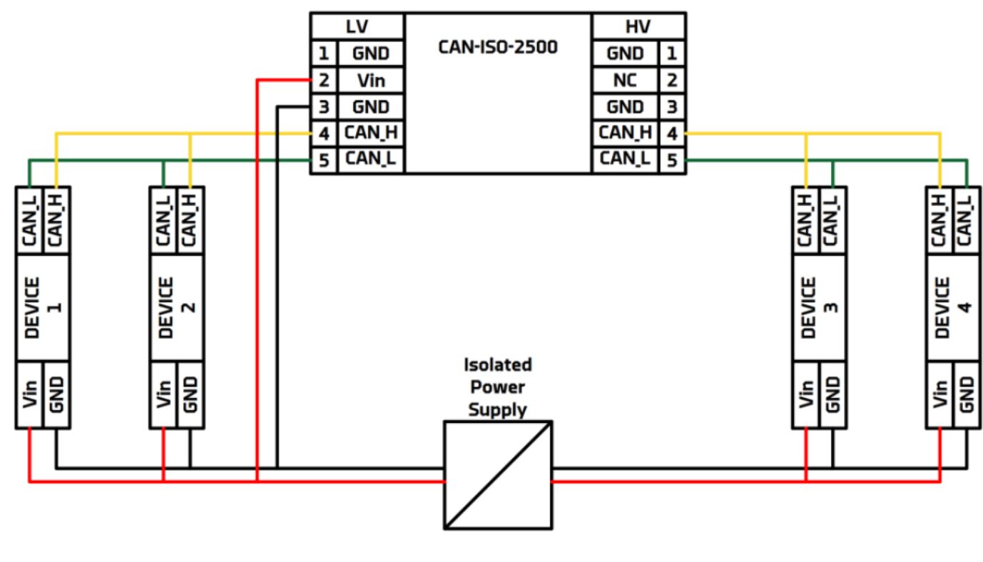
A specific setup was required to ensure consistent results over the range of tests. Since the isolator was designed to pass through CAN messages we connected two USB-TO-CAN devices to a computer and attempted to pass messages between the devices. Then we powered the CAN isolator using an external power supply. Next we wrote some code in python to send and recieve a set of random messages to and from each device in an alternating pattern. In this way we could ensure that the device was working over an extended testing period.
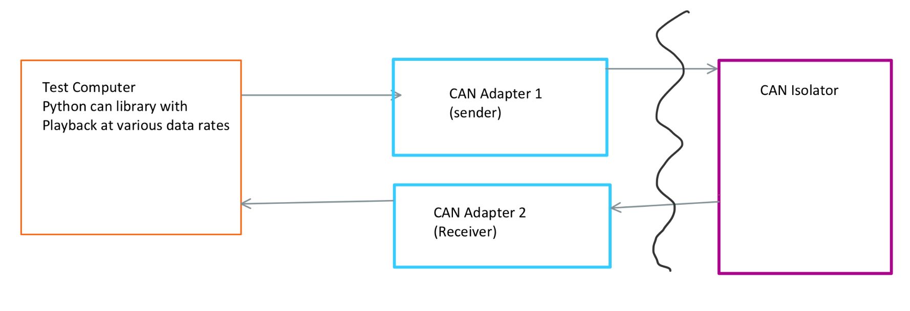
On the computer we ran a basic python script to setup the USB-TO-CAN transcievers. We used the python-can library and a simple loop to send/receive the data.
from datetime import datetime, timedelta
import can
from time import sleep

from helpers import generate_random_message

test_bitrates = [1000000]
num_messages_per_test = 100
time_between_messages = 1 # ms to wait before sending next message
new_message_per_frame = True

bus_0 = can.Bus(interface="ixxat", unique_hardware_id="HW123456", channel=0, bitrate=test_bitrates[0])
bus_1 = can.Bus(interface="ixxat", unique_hardware_id="HW654321", channel=0, bitrate=test_bitrates[0])

print("Starting test at time {}".format(datetime.now()))
print("Test Configuration")
print("\tBaudrates: {} Kbit/s".format(test_bitrates))
print("\tMessages per test : {}".format(num_messages_per_test))
print("\tms between messages : {}".format(time_between_messages))
start_timestamp = datetime.now()
time_delta = timedelta(milliseconds=time_between_messages)
last_message_timestamp = datetime.now()
errors = 0
messages_sent = 0
cycles = 0
try:
    while True: # loop indefinitely until keyboardinterrupt
        for bitrate in test_bitrates: # loop through bitrates
            # bus_0 = can.Bus(interface="ixxat", unique_hardware_id="HW123456", channel=0, bitrate=bitrate)
            # bus_1 = can.Bus(interface="ixxat", unique_hardware_id="HW654321", channel=0, bitrate=bitrate)

            for i in range(num_messages_per_test+1):
                # send from bus0, recieve on bus1
                if new_message_per_frame:
                    message_out = generate_random_message()
                ready = datetime.now() > (last_message_timestamp + time_delta)
                while not ready:
                    ready = datetime.now() > (last_message_timestamp + time_delta)
                bus_0.send(message_out)
                message_in = bus_1.recv()
                last_message_timestamp = datetime.now()
                try:
                    assert message_in.equals(message_out, timestamp_delta=None, check_direction=False, check_channel=False)
                    messages_sent += 1
                except AssertionError:
                    print("Warning: at cycle {}, bitrate {}, send_id: {} recieve_id: {}, messages not equal out: {} | IN: {} |".format(cycles, bitrate, ixxat_ids[0], ixxat_ids[1], message_out, message_in))
                    errors += 1


                # send from bus1, recieve on bus0
                ready = datetime.now() > (last_message_timestamp + time_delta)
                while not ready:
                    ready = datetime.now() > (last_message_timestamp + time_delta)
                bus_1.send(message_out)
                message_in = bus_0.recv()
                last_message_timestamp = datetime.now()
                try:
                    assert message_in.equals(message_out, timestamp_delta=None, check_direction=False, check_channel=False)
                    messages_sent += 1
                except AssertionError:
                    print("Warning: at cycle {}, bitrate {}, send_id: {} recieve_id: {}, messages not equal out: {} | IN: {} |".format(cycles, bitrate, ixxat_ids[1], ixxat_ids[2], message_out, message_in))
                    errors += 1

            print("Success at cycle {}, baudrate {}".format(cycles, bitrate))
            bus_0.shutdown()
            bus_1.shutdown()
        cycles += 1
        print("Cycle {} complete".format(cycles))
        sleep(0.01)

except KeyboardInterrupt:
    print("Stopping test")
    ellapsed = (datetime.now() - start_timestamp).total_seconds()
    print("Sent all messages, sent {} messgaes in {} seconds. AVG: {} msgs/sec".format(messages_sent, ellapsed, messages_sent/ellapsed))
    print("Got: {} errors".format(errors))
    print("Error rate: {}%".format(errors/messages_sent))
Test Cases
- Test all baudrates: tested the device at all possible baudrates.
- Test full range of input voltages: test device at maximum baudrate while changint the power supply input voltage from minimum to maximum value.
- EMC Radiated Emissions: tested per CISPR22
- EMC Field Immunity: tested per IEC61000-4-3
- ESD test: tested per IEC61000-4-2
- HI-POT (High-Potential): voltage isolation test
- On-Vehicle test
The first two test cases were trivial to complete, changing baudrates and input voltages resulted in no data transmission issues.
By far the most challanging test case was the EMC radiated emissions. Multiple board revisions were required to reduce EMC emissions below the CISPR22 required values. The dc-dc converter function within the ADM3053 isolated CAN transciever chip caused high levels of radiated emissions that had to be controlled using careful PCB design and layout.
- The initial tests showed a very high noise peak at around 340 MHz, twice the oscillation frequency of the dc-dc function in the ADM3053.
- The first revision was to move the decoupling capacitors closer to the chip. This helped but did not reduce the noise enough.
- The next revision was done to move the ground planes closer together in an attempt to reduce the noise. This had no noticeable affect on the noise emitted by the device.
- The final revision was to change to a 4-layer PCB with a stitching capacitor similar to the ADM3053 evaluation board. This change significantly reduced radiated emissions to below the CISPR22 Class A emissions level.
After radiated emissions testing the immunity and ESD testing passed with no significant issues.
After EMC and ESD testing was complete a HI-POT test was performed to ensure proper galvanic isolation through the device. For this test the applied voltage was increased from 500-2500v in 500v increments. Zero leakage current was detected in all tests.
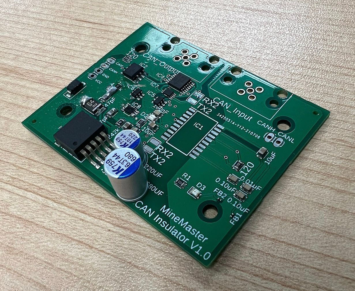
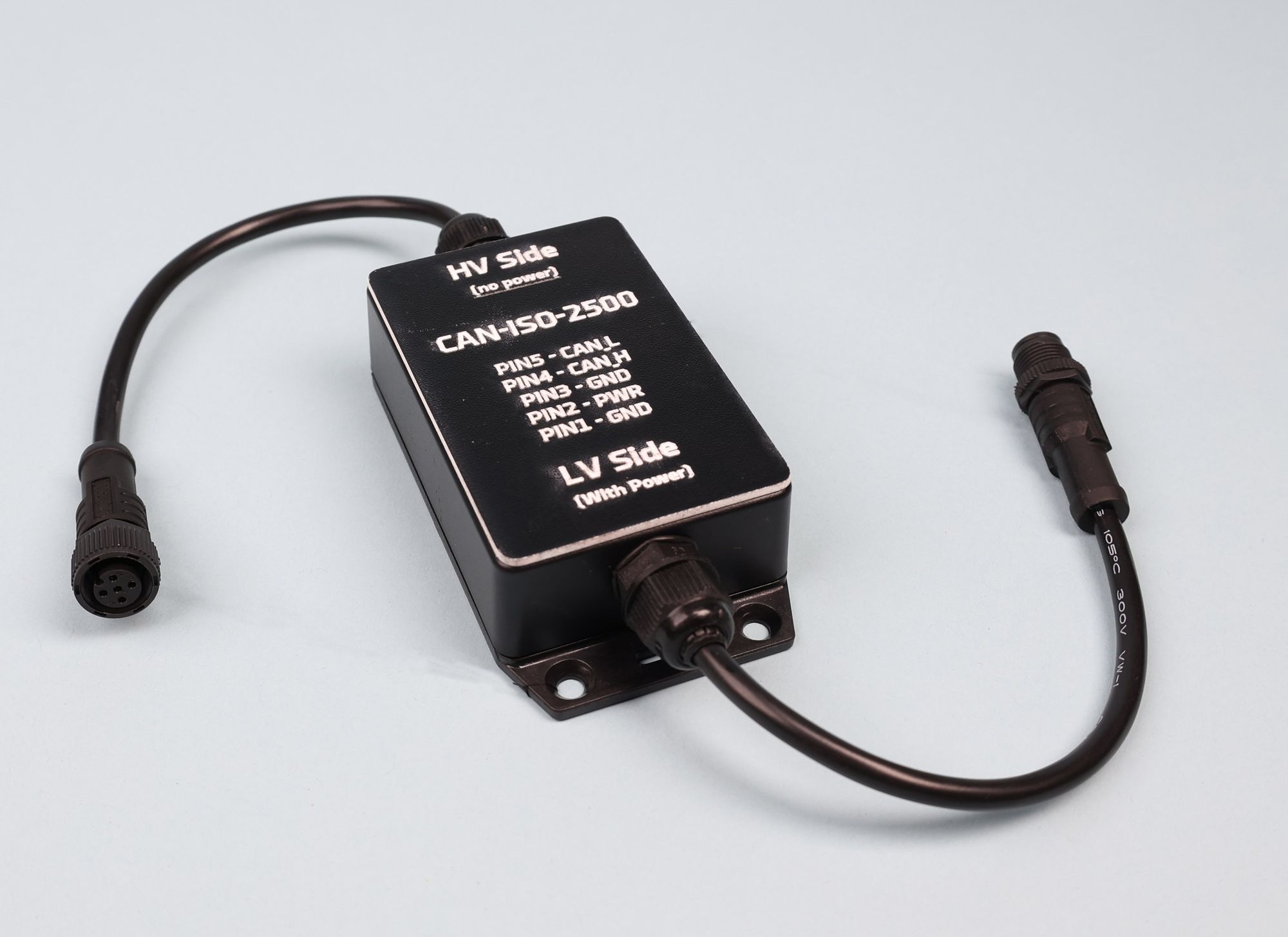
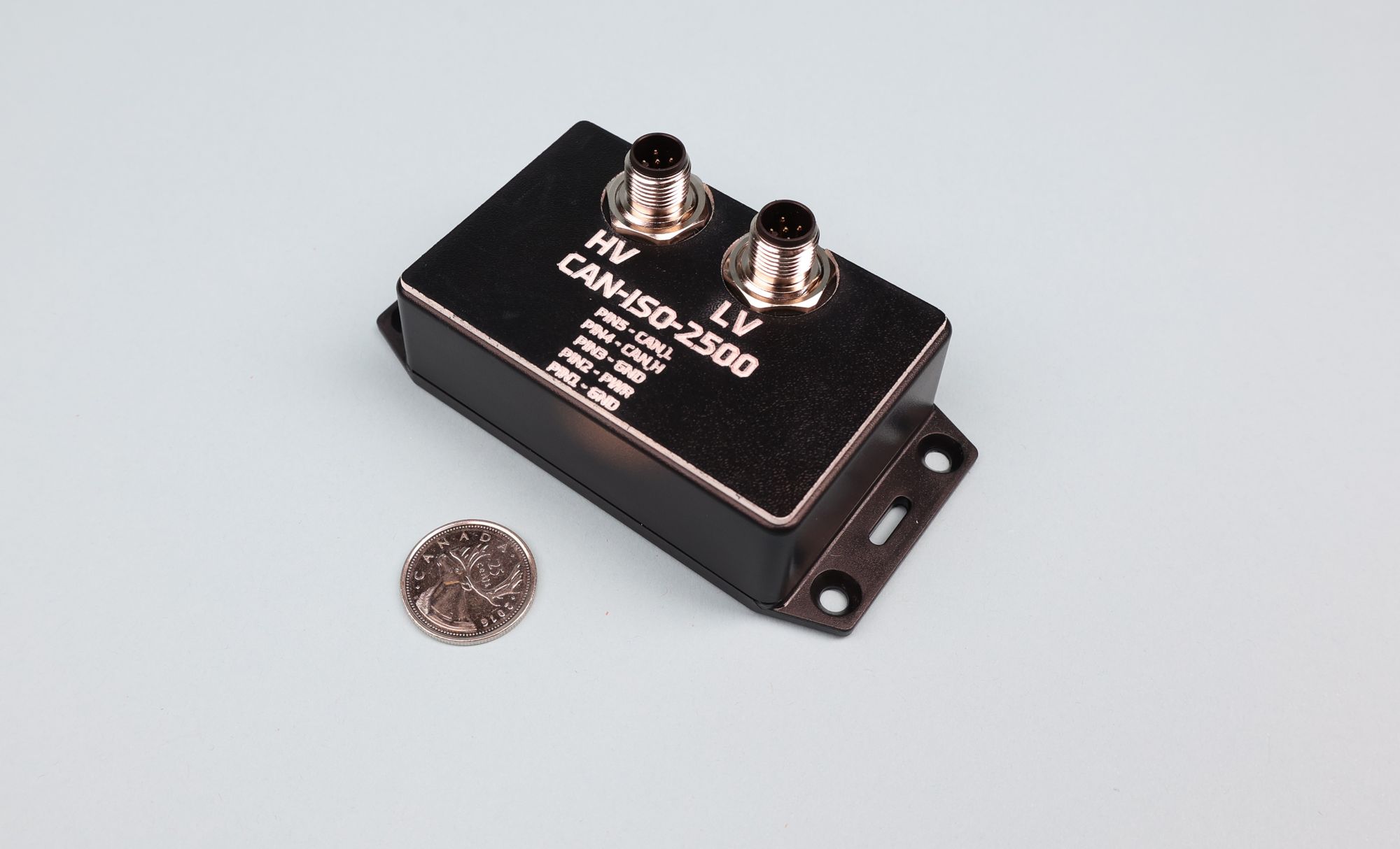
Final Product
The final product of this design project is the CAN-ISO-2500, a fully tested galvanic canbus isolator with a wide input voltage range, IP rated enclosure, high supported datarate, and 2500 volt isolation between sides.
Lessons Learned
- When in doubt always follow the datasheet and reference design. This could have saved a lot of headache and redesigns.
- Testing is critically important: It is easy to get a design that functionally works and stop there. It's important to do EMC testing to ensure the device will not radiate emissions that could affect other systems.
- Iteration is important, don't be discouraged when the initial design has flaws. Build another version and keep testing.
- Build reliable testing systems: Initially the wiring quality of the testing setup was poor, this caused confusion since I didn't know if the errors were caused by the device being tested or the testing setup. A more reliable test setup would have eliminated this time sink.
Enjoying these posts? Subscribe for more
Subscribe nowAlready have an account? Sign in